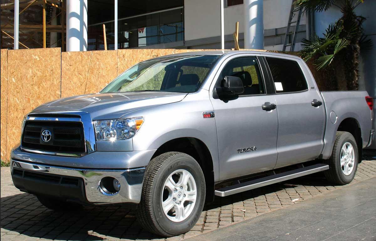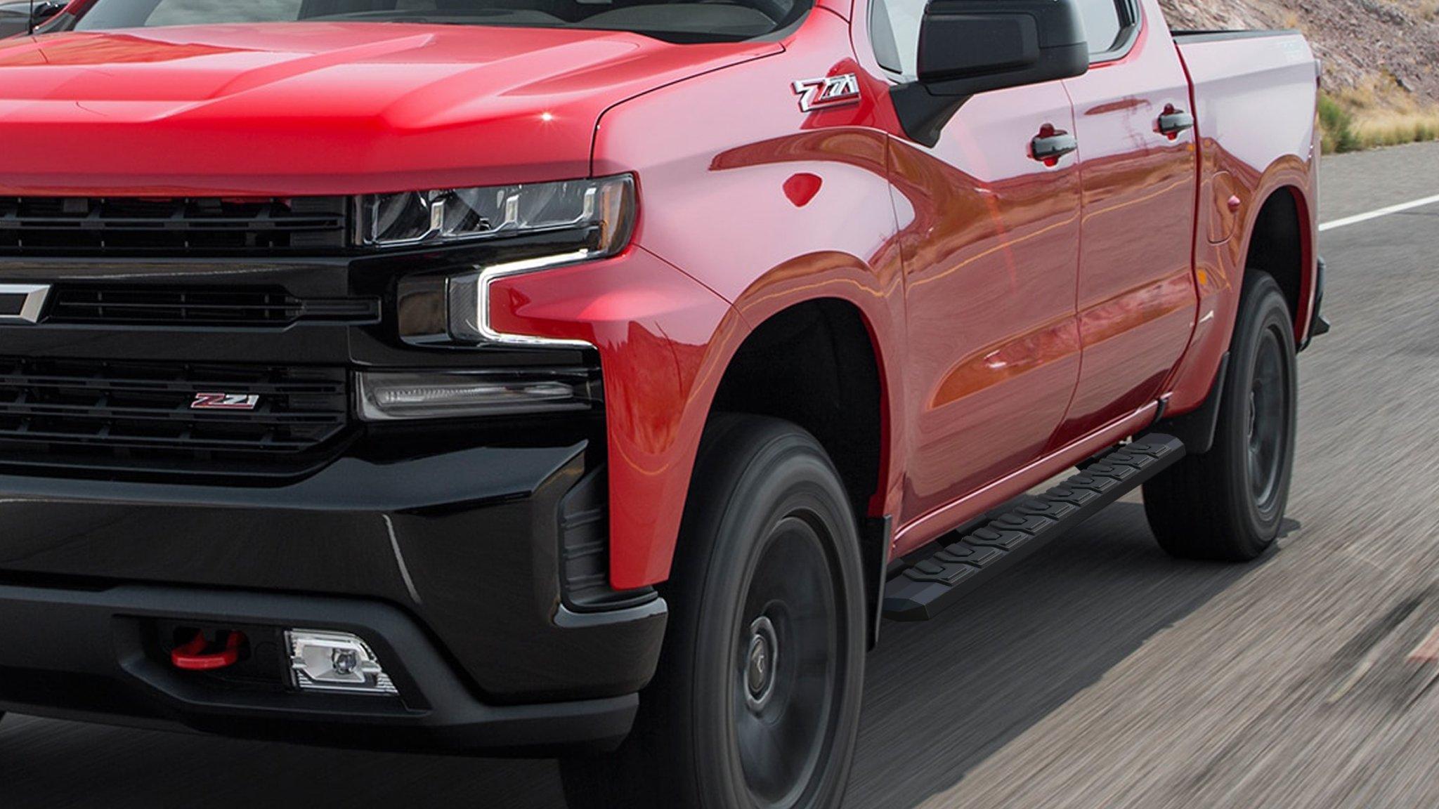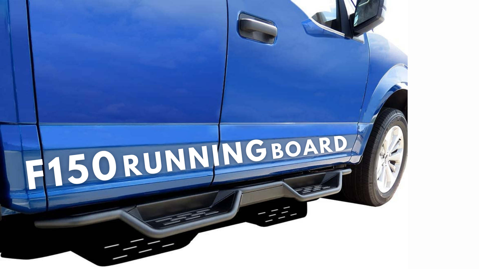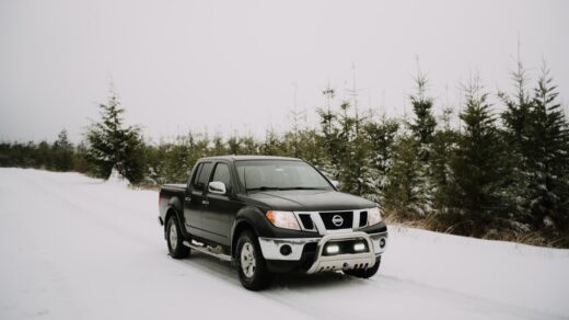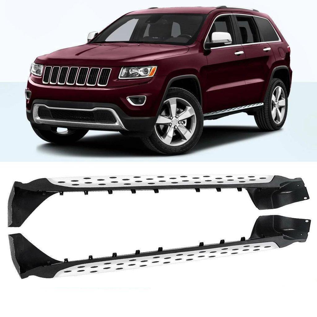
Installing running boards is usually a manageable driveway job when the kit is made for the exact vehicle. The difficult part is not lifting the board into place. It is confirming fitment, assigning each bracket to the correct mounting point, keeping the board parallel to the body and tightening every fastener in the sequence and to the torque specified by the manufacturer.
Most current vehicle-specific kits use existing threaded holes, studs or reinforced openings in the rocker structure. Others require a bolt plate to be inserted through a factory access hole. A universal step may require drilling, but that is a different job with greater corrosion and structural risks. Do not begin by copying a video made for a similar truck: cab length, model year, trim, fuel tank shields and factory options can all change the mounting hardware.
The short answer
To install a typical no-drill running board:
- Match the kit part number to the vehicle year, make, model, cab and side.
- Park on level ground, secure the vehicle and read the complete kit instructions.
- Sort the front, center and rear brackets and their hardware.
- Expose the factory mounting points without enlarging or modifying them.
- Attach every bracket loosely.
- Set the board on the brackets and install its track bolts or mounting bolts loosely.
- Center the board under the doors, level it and check clearance.
- Tighten in the manufacturer's order and to its stated torque values.
- Load-test cautiously and recheck all hardware after the specified break-in period.
The sequence matters. Fully tightening the first bracket before the remaining parts are aligned is one of the fastest ways to create a twisted board, a poor door gap or a rattle.
Can you install running boards yourself?
You can often install fixed, vehicle-specific no-drill boards yourself if you can work safely under the rocker area, identify the supplied hardware and use a torque wrench correctly. Many kits are designed around factory holes and do not require cutting or welding.
Professional installation is the better choice when:
- the instructions require drilling into metal;
- corrosion has damaged a mounting point;
- a captive nut spins inside a closed body section;
- the board is unusually heavy and cannot be supported safely;
- the vehicle has high-voltage components, batteries, fuel lines or wiring near the mounting area;
- the product is powered and needs electrical routing, door-trigger inputs or calibration;
- the kit does not list the exact vehicle configuration.
Running boards are not suitable jack points unless the vehicle or board manufacturer explicitly identifies them as such. A board that supports a person stepping into the cabin is not automatically designed to support the vehicle.
Check fitment before opening every hardware bag
The same truck name can hide several incompatible mounting patterns. Verify all of the following:
- model year and generation;
- make and model;
- regular, extended or crew cab;
- gas, diesel, hybrid or electric powertrain where the application guide distinguishes them;
- body-on-frame or unibody version;
- factory rocker cladding, mud guards, side skirts or existing steps;
- left and right board lengths;
- fixed versus powered board kit;
- bracket kit and board kit compatibility.
ARIES, for example, uses vehicle-specific brackets in several systems and publishes application guides that pair individual bracket numbers with compatible boards. That illustrates why a board that physically looks long enough is not proof that its mounting kit fits your vehicle.
Before installation, hold each bracket near its intended location without forcing it. The hole spacing and bracket contour should agree with the instruction diagram. If the parts only line up after bending, drilling or loading a bolt sideways, stop and verify the kit number.
Tools and supplies
Use the tool list in the product instructions as the authority. A typical fixed-board installation may need:
- wheel chocks;
- safety glasses and work gloves;
- metric and/or SAE sockets and combination wrenches;
- a ratchet and suitable extensions;
- a calibrated torque wrench covering the specified range;
- trim tools for plastic plugs or covers;
- a soft support, second person or adjustable stand for the board;
- a nylon brush and penetrating oil for dirty exposed threads;
- rust-inhibiting primer only if the approved procedure exposes bare steel.
An impact wrench can be useful for removal work, but it is a poor final-tightening tool. It makes it easy to cross-thread a captive nut, crush a bracket slot or exceed the torque specification. Start every fastener by hand and use a torque wrench for the final pass.
Prepare the vehicle safely
Park on a firm, level surface. Apply the parking brake, select Park or first gear as appropriate and chock a wheel. Turn the ignition off and keep the key away from powered steps that could deploy unexpectedly.
Many fixed-board installations can be completed with the vehicle on the ground. If additional access is genuinely required, lift only at approved points and support the vehicle with appropriately rated stands on a stable surface. Never work beneath a vehicle held only by a jack.
Clean mud, road salt and undercoating residue from the mounting area. Photograph the underside before removing plugs, shields or factory fasteners. That record is useful if two holes look similar or a shield must be returned to its original position.
Lay out the brackets and hardware

Do not treat all brackets as interchangeable. A kit can use different front, center and rear offsets even when the pieces look nearly identical. It may also include mirrored left- and right-side parts.
Arrange the components on the floor in vehicle order. Keep the hardware for each mounting point in a separate tray. Compare stamped marks, bends and slot direction with the instruction sheet. Confirm whether washers sit against the bracket, the body or both.
If the kit uses bolt plates or clip nuts inside an access opening, attach any supplied pull wire before inserting the hardware. Keep control of the wire until the nut is started. Dropping a bolt plate into a closed rocker can turn a short installation into a difficult retrieval job.
Step-by-step: install fixed no-drill running boards
1. Expose the factory mounting points
Remove only the plugs, tape patches, trim screws or factory bolts identified in the instructions. Do not assume every opening along the pinch weld is structural. Some are drains or manufacturing holes.
If a threaded hole is packed with dirt, clean it gently and test the supplied bolt by hand. Resistance after the first turn can indicate the wrong thread pitch or a cross-thread. Do not force it with a power tool.
2. Install every body bracket loosely
Attach the front, center and rear brackets with the specified washers and retainers. Thread each bolt several turns, but leave enough movement for alignment. Where a bracket also meets the pinch weld, install that hardware without pulling the metal out of shape.
The bracket should sit flat against its intended surface. A gap caused by seam sealer may be normal if the instructions show it; a bracket rocking on a wiring clip, plastic trim or fuel-line retainer is not.
3. Prepare the running board
Some boards use bolts that slide into channels on the underside. Insert the correct number, orient their heads in the track and roughly space them to match the brackets. Install end caps or trim only at the stage specified by the manufacturer; fitting them too early can block access to the channels.
Check which end faces forward. Tapered ends, step-pad placement and drain openings are not always symmetrical.
4. Place the board on the brackets
Use a helper or a padded stand so the board cannot fall against the paint. Guide the track bolts through the bracket slots, add the washers and nuts, and start each nut by hand. Do not tighten one end yet.
For a two-piece system, install any board-to-mounting-rail hardware in the specified order. The board may need to slide longitudinally before the end cap is installed.
5. Center the useful step area
Close every door gently and inspect where passengers naturally place a foot. Center the board across the door openings rather than aligning it only to a wheel arch. On crew-cab trucks, confirm that the rear step pad remains useful without allowing the front edge to interfere with a mud flap or front tire at full steering lock.
Measure the gap from the rocker or pinch weld at the front and rear. The board should appear parallel to the body when viewed from the side. Compare left and right overhang, but remember that exhaust or body shapes can make a perfectly installed pair look slightly different from underneath.
6. Set inboard-outboard position and clearance
Move the board within the bracket slots to achieve the approved body clearance. Leave room for door movement, rocker flex, snow and mud. A board mounted too far inward can rub trim; too far outward increases leverage on the brackets and may place the step surface beyond the intended position.
Check all doors, factory mud flaps and any front wheel clearance before tightening. Do not use the board to push flexible body trim into a new position.
7. Tighten in stages

Follow the kit's sequence. A sound general method is to snug the board-to-bracket hardware, snug the brackets to the vehicle, recheck alignment, then torque each fastener to the value in the instructions. The actual torque depends on bolt size, grade, coating and mounting structure, so there is no safe universal number.
Hold the board in position while tightening. Alternate between mounting points instead of finishing one end before the other. Paint-marking each torqued bolt can make the final inspection easier, but the mark is not a substitute for measured torque.
8. Test before normal use
Press down by hand at each mounting point and listen for movement. Then apply body weight gradually while holding a stable part of the vehicle. Do not jump on the board. Verify that it does not contact the body and that every bracket shares the load.
Repeat the inspection on the opposite side. After the interval specified by the manufacturer, recheck torque and alignment. Inspect sooner if the board shifts, clicks or is struck off-road.
What changes for powered running boards?
Powered steps add motors, linkages, a controller and wiring. Mechanical fitment is still vehicle-specific, but the electrical work makes the process less universal.
Typical additional tasks can include:
- disconnecting the 12-volt battery in the specified order;
- mounting motors and linkages on designated sides;
- routing a fused harness away from exhaust, steering and moving suspension parts;
- making weather-sealed connections;
- connecting through an approved diagnostic or door-trigger interface;
- calibrating the deployed and stowed positions;
- testing obstacle response and each door independently.
Do not probe random door wires or splice into a CAN bus because an online video used the same wire color on another model year. Use the current instructions for the exact kit and vehicle. On hybrid and electric vehicles, orange high-voltage wiring and battery structures require special caution.
What if the kit requires drilling?
Confirm that drilling is genuinely part of the official installation, not an attempt to make an incorrect bracket fit. Inspect both sides of the proposed hole for wiring, brake lines, fuel lines, airbags, batteries and structural reinforcements. Mark from the bracket only after the board alignment is proven.
Use the specified hole size, control the drill depth, deburr the opening and protect exposed steel with an appropriate corrosion coating. Metal chips should be removed from cavities and painted surfaces. If the instructions require a rivnut, use the correct setting tool; a loose or over-crushed insert will not provide a reliable mount.
Drilling a leased vehicle, a corrosion-sensitive rocker or a structural area is a good reason to use a professional installer.
Common installation mistakes
Buying by board length instead of application
A long enough board can still have the wrong track, bracket spacing or load path. Match both the board and bracket part numbers.
Tightening brackets before the board is aligned
This removes the adjustment needed to center and level the board. Leave all joints movable until the complete assembly is in place.
Mixing left, right, front and rear brackets
Small offset differences become large alignment problems at the outer edge of the board. Sort components before installation.
Using a guessed torque value
The correct value depends on the supplied hardware and the vehicle attachment. Use the current instruction sheet, not a generic chart alone.
Pinching wiring or blocking drains
A bracket can appear to fit while trapping a harness or covering a rocker drain. Inspect the full contact area with a light before tightening.
Treating the board as recovery equipment
Ordinary running boards are access steps. Do not attach tow straps, jack from them or use them as rock sliders unless the product is specifically engineered and rated for that purpose.
How to stop a running board from rattling
First identify whether the noise comes from the board-to-bracket joint, the bracket-to-body mount, a loose end cap or contact with trim. Check for shiny witness marks around the suspected area.
Verify that every supplied washer and spacer is present, the brackets are in their correct positions and the board is not preloaded against the body. Re-torque to the manufacturer's values. Do not cure a structural rattle with random rubber pieces or permanent adhesive; those can conceal a loose joint and alter the load path.
On powered boards, inspect linkage play and confirm that the step reaches its calibrated stowed position. Motor or controller faults require the product-specific diagnostic process.
Frequently asked questions
How long does it take to install running boards?
A straightforward no-drill fixed kit can often be installed in one to three hours, but corrosion, heavy boards, powered wiring and unclear bracket identification can extend the job. Manufacturer time estimates assume the correct kit and suitable tools.
Do running boards use existing holes?
Many vehicle-specific kits do. They may use factory threaded holes, studs or access openings for bolt plates. Universal and some older applications can require drilling.
Should I use threadlocker?
Only if the manufacturer specifies the correct type. Some supplied nuts are mechanically locking, and adding a lubricant or threadlocker can change the relationship between torque and clamp load.
Can running boards be mounted to the pinch weld?
Some kits use the pinch weld as one part of a designed mounting system. Do not clamp or drill it unless the vehicle-specific instructions show the exact locations and hardware.
Why is one running board lower than the other?
Common causes are swapped brackets, a bracket installed on the wrong side of a body seam, uneven track-bolt positions or a loose vehicle mount. Compare the instructions and measurements before adding spacers that were not supplied.
Bottom line
The best running-board installation is deliberately uneventful: the correct vehicle-specific kit, all brackets started loosely, the board centered under the doors, clearances checked and every fastener torqued from the manufacturer's instructions. If the parts require force or improvisation to line up, stop and confirm fitment before modifying the vehicle.
Sources for editorial review
- ARIES Automotive, VersaTrac vehicle-specific mounting brackets and install resources: https://www.ariesautomotive.com/part/2055101
- ARIES Automotive, ActionTrac vehicle-specific powered-board brackets: https://www.ariesautomotive.com/part/3025152
- ARIES Automotive, running-board and compatible-bracket application guide: https://www.ariesautomotive.com/masterlibrary/01resources/appguides/ARIES/VersaTrac_Brackets_%26_Compatible_Boards_Application_Guide.pdf
Internal links
- Link
dashboard warning lightsto/dashboard-warning-lights-explained/where electrical warnings are discussed. - Link
truck-bed coverto/how-to-install-tonneau-covers/from a contextual accessories paragraph. - Future supporting page:
/running-boards-vs-side-steps/.